Fax: (0 80 36) 9 08 20- 28
E-Mail: info@bbw-lasertechnik.de
Gewerbering 11
83134 Prutting
In contract manufacturing of small orders, the handling time of the parts often exceeds the actual welding time by a factor of 10 or more. This is balanced out in partially or fully automated large-scale production. The most obvious adjustment screw is to increase the welding speed while simultaneously increasing the laser power. The laser power limit can be overcome by purchasing more powerful beam sources, but there is still a physical speed limit in the range of 400-600 mm/s for most types of material due to the so-called humping effect. Read our new blog post to find out what is behind this and how the humping effect can still be circumvented.
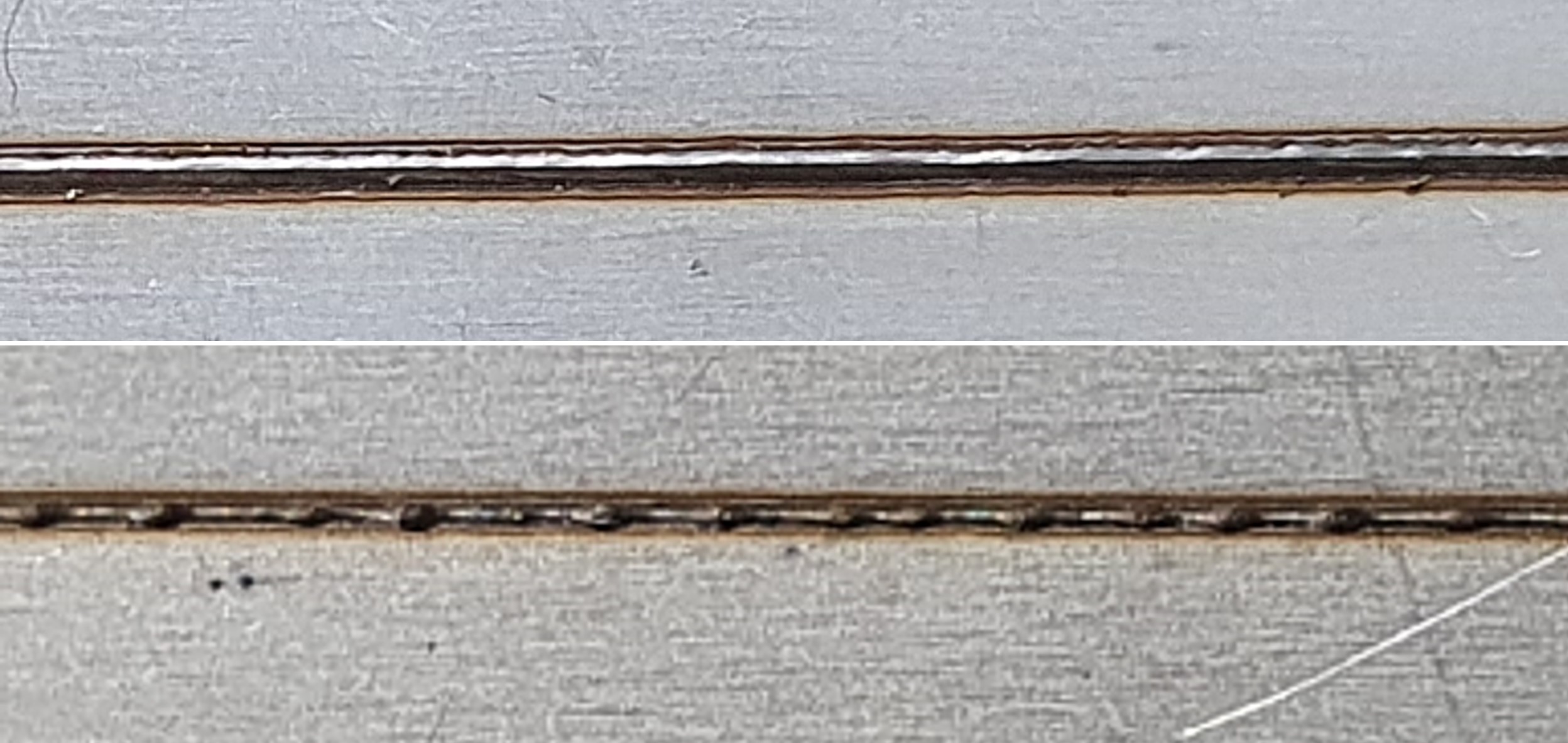
Humping is the phenomenon of a periodic weld seam irregularity, the exact origin of which is the subject of various discussions. At very high welding speeds, the weld pool rises or the seam collapses at periodic intervals. A limit speed can be defined for the occurrence of humping, but this depends on the material, focus diameter and other factors.
Periodic seam bulging at high welding speeds
While typical seam irregularities such as pores are statistically distributed (see previous blog posts) and can already occur at medium speeds, periodic irregularities of the seam surface are recognizable at very high speeds (Neumann, 2011).

There are various theories for the origin of the humping effect: Fabbro et. al (2007) and Beck (1996), for example, describe the observation of metal vapor hitting the back of the capillary at high velocities and causing wave crests, which then solidify. Speth et. al. (2009), on the other hand, cite the achievable wetting angle of a melt droplet in connection with the surface tension as a critical formation variable. However, it is generally agreed that an interplay of capillary forces and melt pool dynamics causes this effect.
Influencing the humping limit by choosing the right laser parameters
In simple terms, a humping limit speed can be defined above which these periodic effects occur. However, the limiting speed can be influenced by various factors. A lower laser power and a larger focus diameter generally result in a higher humping limit speed. The choice of substrate also produces different results: Steel and nickel have a noticeably lower limiting speed than titanium and aluminum. There are also considerations that a superimposed wobbling technique can prevent humping, although this requires highly dynamic scanners with wobbling frequencies >5 kHz.
An alternative is to heat the substrate surface, which can also achieve higher humping threshold speeds.
Test result from BBW Lasertechnik: Concentric beam superimposition leads to a more than 100 % higher humping limit
The fact that heating the surrounding material areas leads to a significantly higher limiting speed has already been demonstrated in various studies using two laser spots. According to Neumann (2011), the best results were achieved when both beams overlap concentrically and the heating beam is larger than the laser beam for the welding process. Various laser manufacturers now offer precisely such solutions with 2-in-1 fiber technology (more information on this in our previous blog articles). BBW Lasertechnik uses AMB technology from IPG and Brightline technology from Trumpf for this purpose.
We therefore found the opportunity to recently test the 2-in-1 fiber technology in conjunction with a single-mode laser source from IPG in their application center very interesting. As humping effects are to be expected at a very small focus diameter, which is usual for a single-mode laser, the possibility of heating by means of an additional ring intensity is very promising.

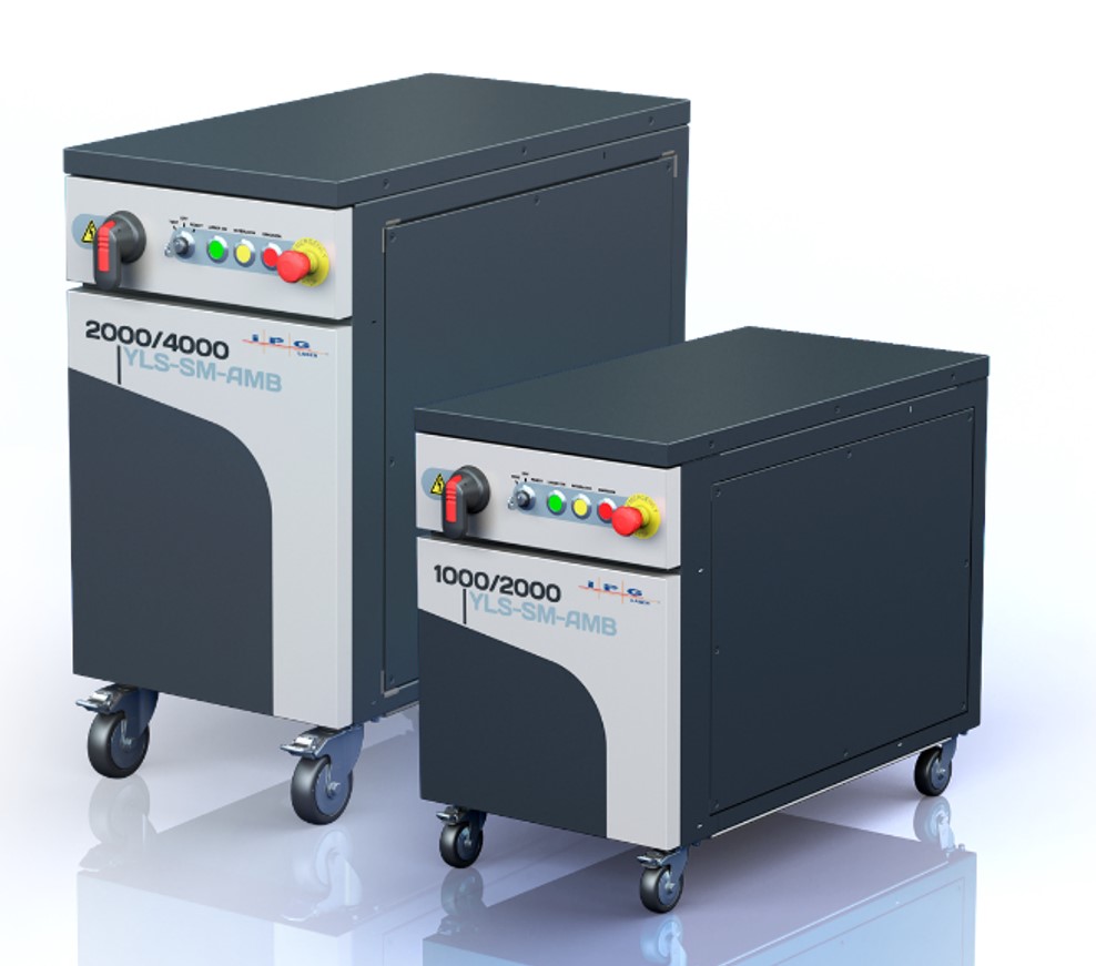
The tests were carried out with a YLS-2000/4000-SM-AMB fiber laser (Figure 2, left), which means that 2 kW is available for the core fiber and 4 kW for the ring fiber. A very small spot diameter of 25 µm was achieved via the singlemode core fibre, while a further ring spot of approx. 180 µm was realized via the multimode ring fibre, which corresponds to a ratio of 1:7.
In the welding tests, 2 x 0.5 mm steel sheets were placed on top of each other and welded together. By adjusting the power and speed, a comparable welding depth was achieved and the humping limit speed was compared with pure single-mode intensity and with AMB switched on.

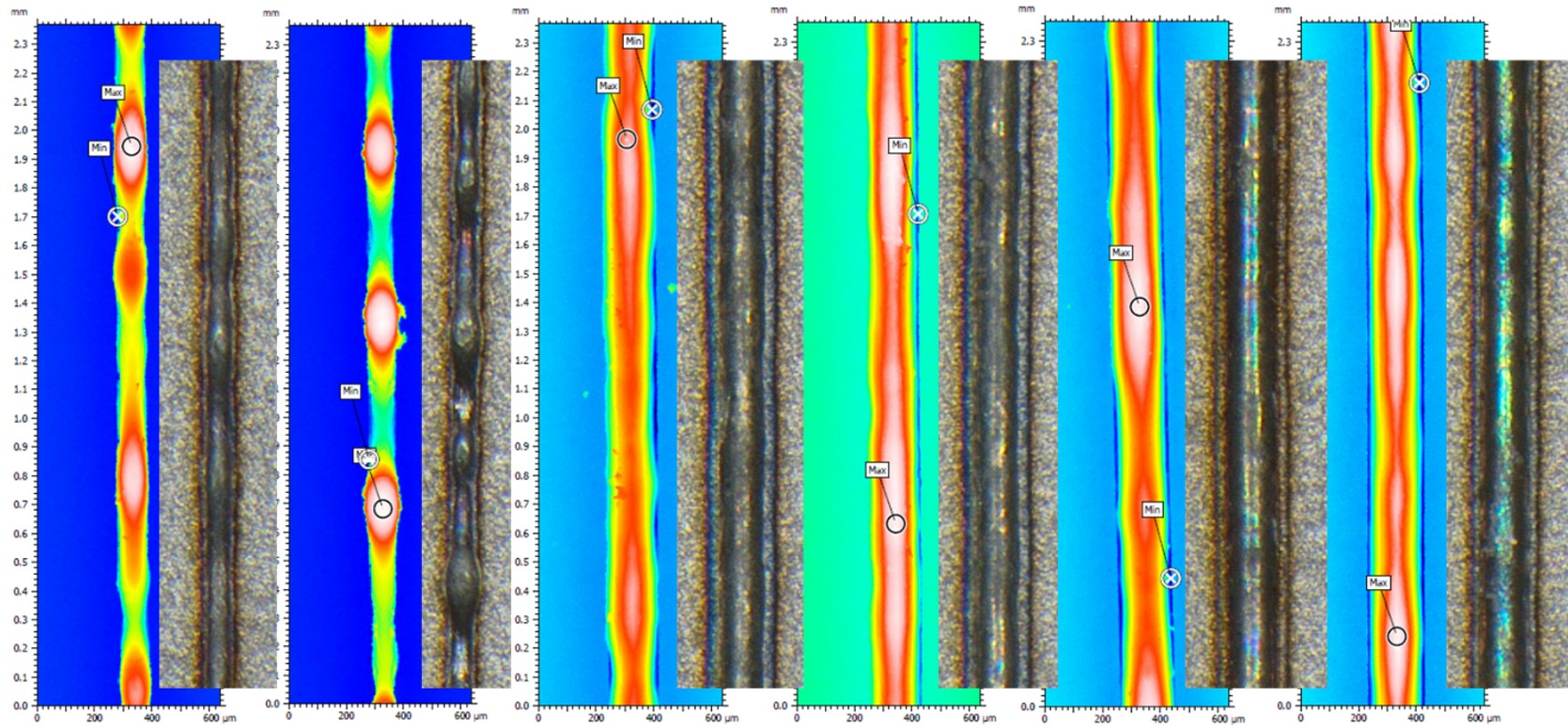
The completed welds were subsequently evaluated at BBW Lasertechnik using our metallography and confocal measurements. However, it was already apparent in the application laboratory that the humping effects with an additional ring intensity only occur at limit speeds that are more than 100 % above the limit without AMB. An inspiring result!
Conclusion
Possible welding speeds of 1 m/s or more are particularly interesting when large welding distances have to be realized with a single-mode laser. This is the case, for example, with large bipolar plates or radiator plates that are installed in electric vehicles. Several dozen meters of welding distance can quickly add up here.
A contribution by Eric Punzel
Quellen:
[1] Neumann, S.: Einflussanalyse beim single mode Faserlaserschweißen zur Vermeidung des Humping-Phänomens, Dissertation, 2011, Universität Bremen
[2] Fabbro, R. et. al: Experimental study of the humping process during Nd:Yag laser welding. In: Proc. 4th int. WLT-Conference on LIM, München 2007, 277 – 282.
[3] Beck, M.: Modellierung des Lasertiefschweißens, Dissertation, 1996, Stuttgart.
[4] Speth, R. K. et. al: Capillary Instability on a hydrophilic stripe. New. J. Phys., 11, 2009, 075024.
Sources:
[1] Neumann, S.: Influence analysis in single mode fiber laser welding to avoid the humping phenomenon, dissertation, 2011, University of Bremen
[2] Fabbro, R. et. al: Experimental study of the humping process during Nd:Yag laser welding. In: Proc. 4th int. WLT-Conference on LIM, Munich 2007, 277 - 282.
[3] Beck, M.: Modellierung des Lasertiefschweißens, Dissertation, 1996, Stuttgart.
[4] Speth, R. K. et. al: Capillary Instability on a hydrophilic stripe. New. J. Phys., 11, 2009, 075024.